Please check before you start and make sure all the parts are present, if not let us know and we'll hunt them down.
Please also check the soldering of the USB serial chip that has already been soldered onto your board, make sure that none of the pins around it have been shorted
Safety:
The most important secret to soldering is to understand that the things that are being soldered together (pads on a printed circuit board and leads of a component) both need to be hot enough to melt solder - so touch your soldering iron to the board and the component, wait a bit then melt a little solder into the join. Remove the soldering iron quickly - overheating can damage components or cause traces to lift off the board.
Once you're done with a solder join snip the excess component leads and move on to the next component
I usually start with the parts that stick the least above the board then work outwards - this way when you place the board upside down to solder parts they stay in place more easily. However we start beginners with the main CPU because it is an easy piece first soldering.

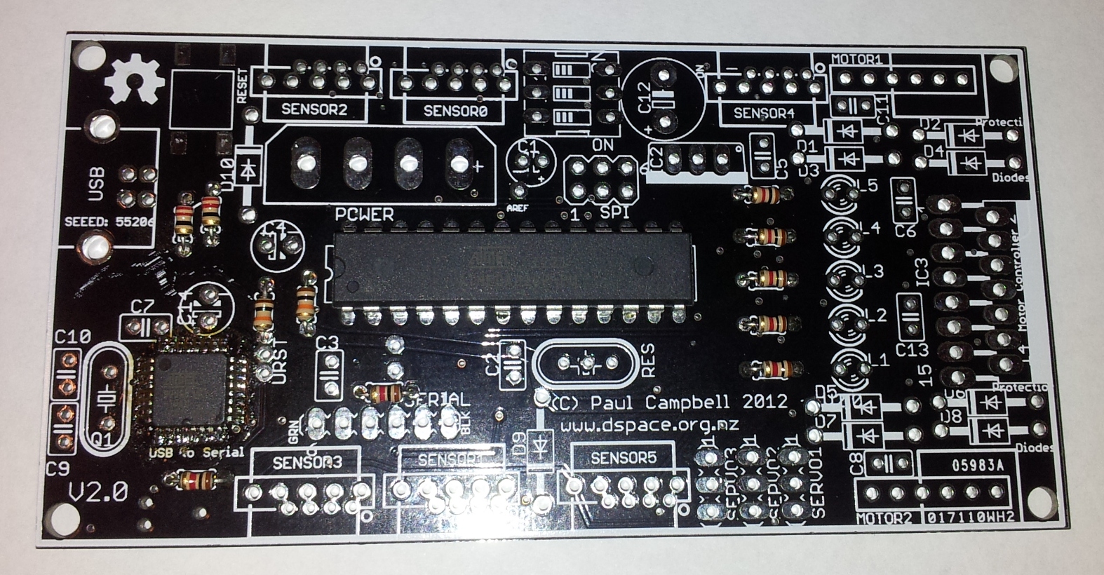
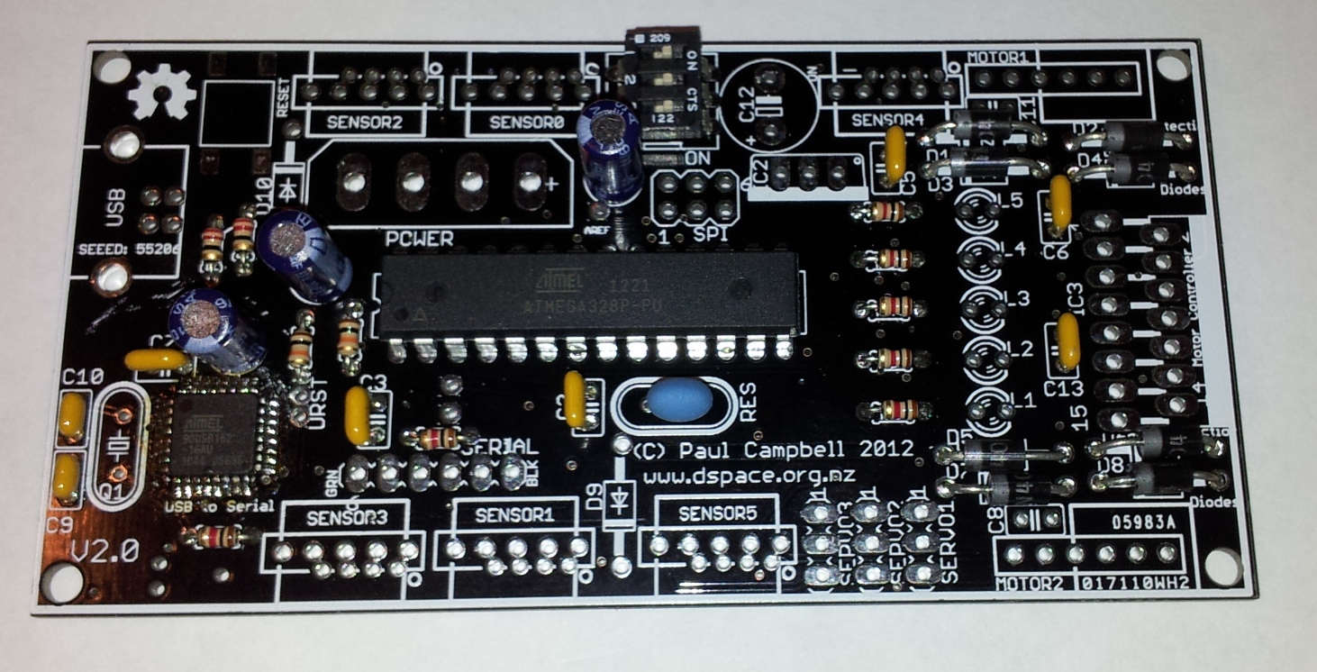
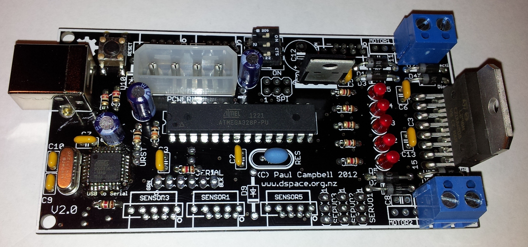
Look at how the board is aligned in the picture above, when we talk about "left", "right", "up" and "down" we expect it to be this way around.
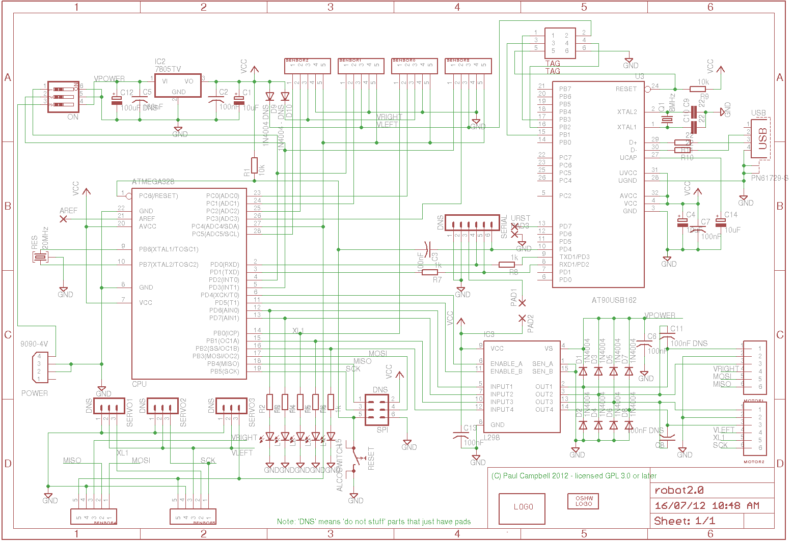
The printed circuit board comes with the USB serial CPU already soldered on to it - quickly inspect it, are any of the pins shorted? (it's OK if the two pins next to C7 are connected, all the rest should seperate) - if you see a problem send it backThe schematic for what we're building is also available. And if you have a copy of the Eagle CAD program you can look at the layout as well (look in the downloads section)
IMPORTANT: The CPU must go in the right way around look for the notch on the package and the round dot and install it with them matching up with the same marks on the board - facing to the left.
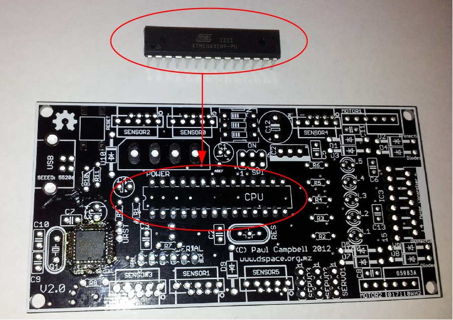
If you haven't soldered before take it carefully - place the chip's pins through the board (see the picture below), you may have to very gently bend them to get them to fit, don't bend them too much, they will break. Bend a couple of pins a little underneath to hold it the chip place and turn the board upside down, check to make sure that all the pins are sticking through their holes. Solder a pin at one corner - remember heat the pin and the pad on the circuit board until the solder melts on them (rather than on the soldering iron) - don't heat the chip too long, you can damage it - get in and out as quickly as you can. Now solder the diagonally opposite pin - turn the board over and make sure the chip is seated correctly, if not press on it while you heat a pin. Now work around the chip soldering all the rest ofthe pins.
Use the least amount of solder you can, just enough to flow onto the pad and around the pins - it should end up looking something like this:

There are 3 sorts of resistors, they can go in any way around
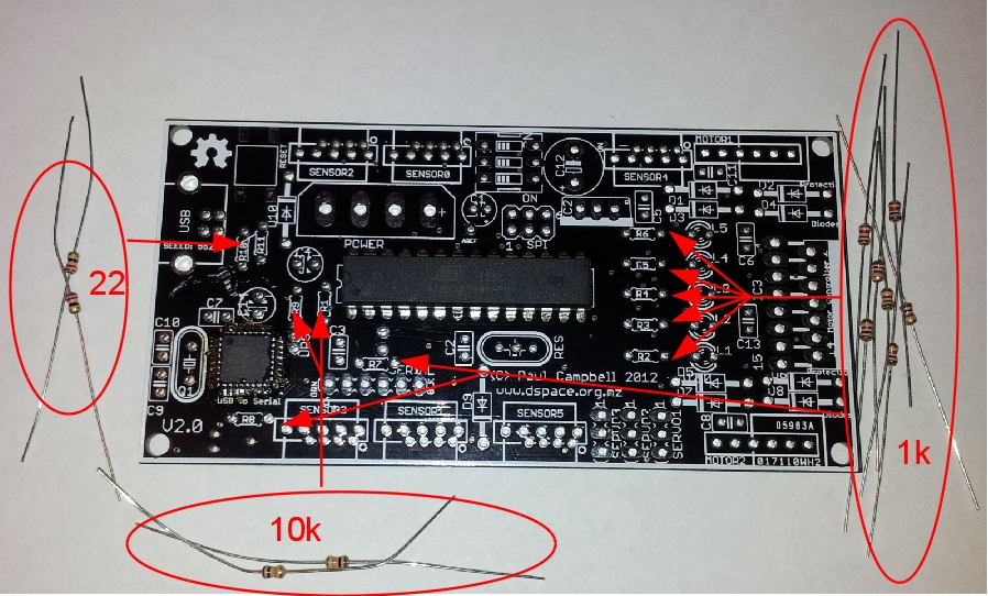
R10 and R11 are 22 ohm resistors (red-red-black) - they go in the middle left of the board. R1 and R9 are 10k resistrors (brown-black-orange), they go in the space between the two chips. All the rest of the chips are 1K (brown-black-red) R2, R3, R4, R5 and R6 go to the right of the main CPU, R7 goes below it and R8 is below the USB serial chip.
There are two sorts of disc ceramic capacitors - 18pf - look for a '18' on them, they're beige coloured in the picture below - C9 and C10 are to the lower left of the board. Some kits may come with 22pF capacitors instead of 18pF ones.
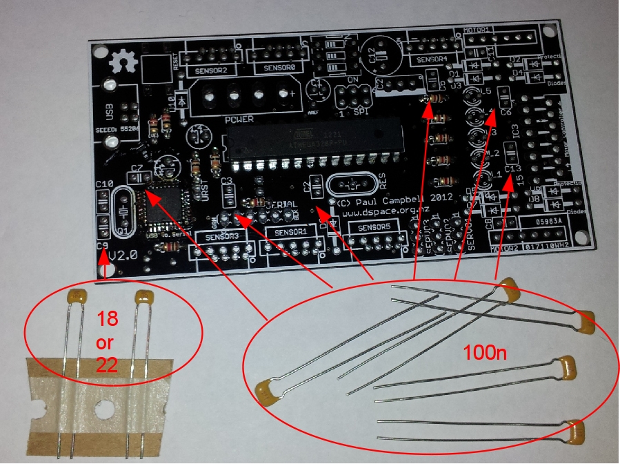
The rest of the disc ceramics are 100nF - labelled '104', install 100nF caps in C7, C3, C2, C5, C6 and C13. They may be beige or blue depending on the source.
All these capacitors above can go in either way around
The resonator RES is the 3 pin blue or beige coloured part, it goes below the main CPU. It doesn't matter which way around this goes.
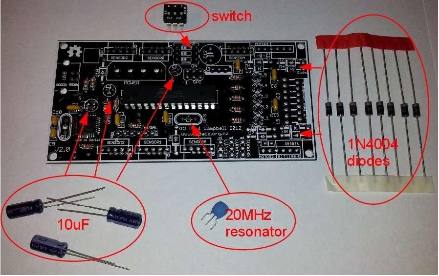
C1 a 10uF capacitor goes above the CPU - it must go in the right way around - look for the -ve and +ve sides. Traditionally capacitors like this have their -ve side marked with a stripe with "-" signs in itand the board is only marked on the +ve side.
Look at the picture below: the gray stripe is the negative side of the capacitor.
C4 and C14 are also 10uF capacitors, one goes above the USB serial processor, the other to the left of the main CPU
NOTE: C14 - the 10uF capacitor on the left in the photo below is shown inserted BACKWARDS - the +/- on the board is correct
The 3 bit DIP switch goes in the middle at the top - put the side marked 'on' closest to the 'on' marked on the board.
The 8 protection diodes D1-D8 go in two groups of 4 on the right side - they too must go in the right way around - look for the band marked at one end and the matching band on the image on the board. There are two other spaces for diode D9 and D10 - LEAVE THESE EMPTY for now
The USB connector goes to the left of the board, there's only one way it can go around
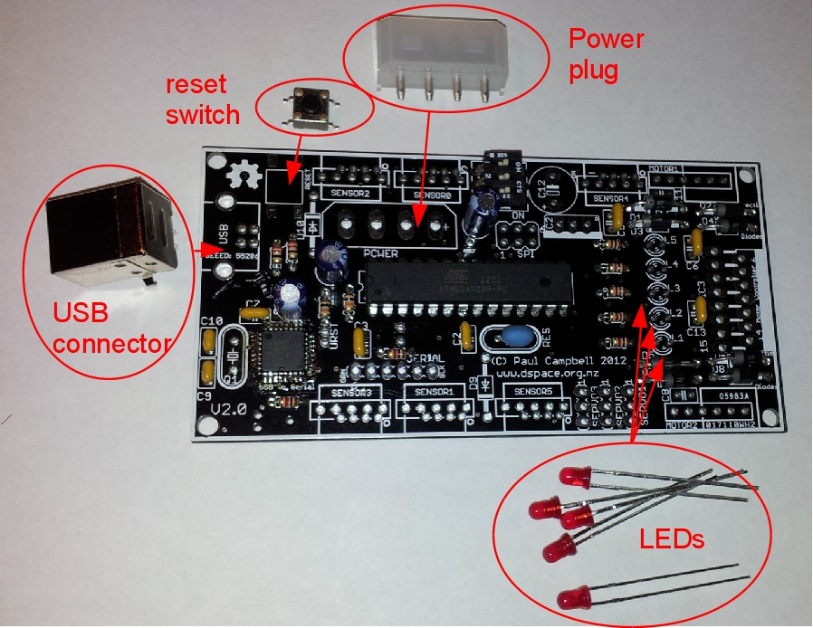
The reset switch goes above it - it can go either way around - solder one corner, get it sitting right then solder the other 3 corners
Put the power socket in the right way around (look at its shape).
The 5 LEDs L1-L5 have to go in the right way around - LEDs have a number of ways to tell which pin is which - normally one leg is longer, sometimes one side of the LED is flat (the flat side is on the side with the shorter leg). On these boards the image of the led is not quite round, one side is flattened - it's the right hand side of the image of the LED on the board (the side next to the 'L1', 'L2', ... labels ) put the LEDs in with the short leg on the 'flat' side - to the right, next to the label. Some kits may have transparent LEDs.
Q1 the 8Mhz crystal (oval silver device) for the USB serial CPU goes to the left of the board, it doesn't matter which way around it goes
The 5 volt voltage regulator (7805) goes in IC2 - the flat metal side goes over the white bar on the image on the board
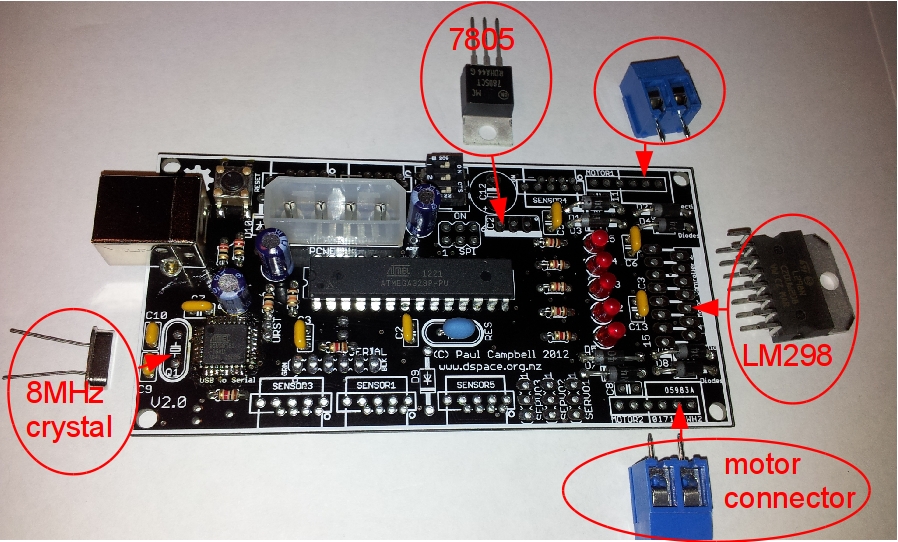
The L298 motor controller goes to the right - it mounts vertically, make sure the pins don't short.
The kit comes with 4 2-pin terminal blocks - only install 2 of them, MOTOR1 and MOTOR2 for the moment. Leave them off if you plan on using Lego motors with tachometers. The board has 6 holes for MOTOR1 and MOTOR2 - if you're soldering in terminal blocks they go the the rightmost pin of the socket - look at the top of the board there's an outline that matches the bottom of the terminal block, use that as a guide. Make sure that the holes on the side of the terminal blocks are facing outwards, away frok the motor controller IC.
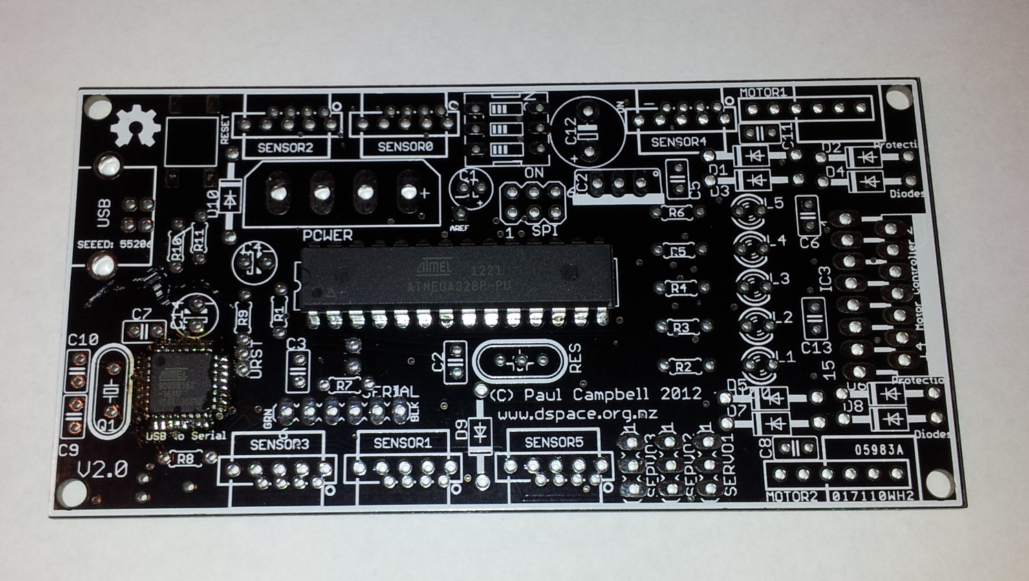
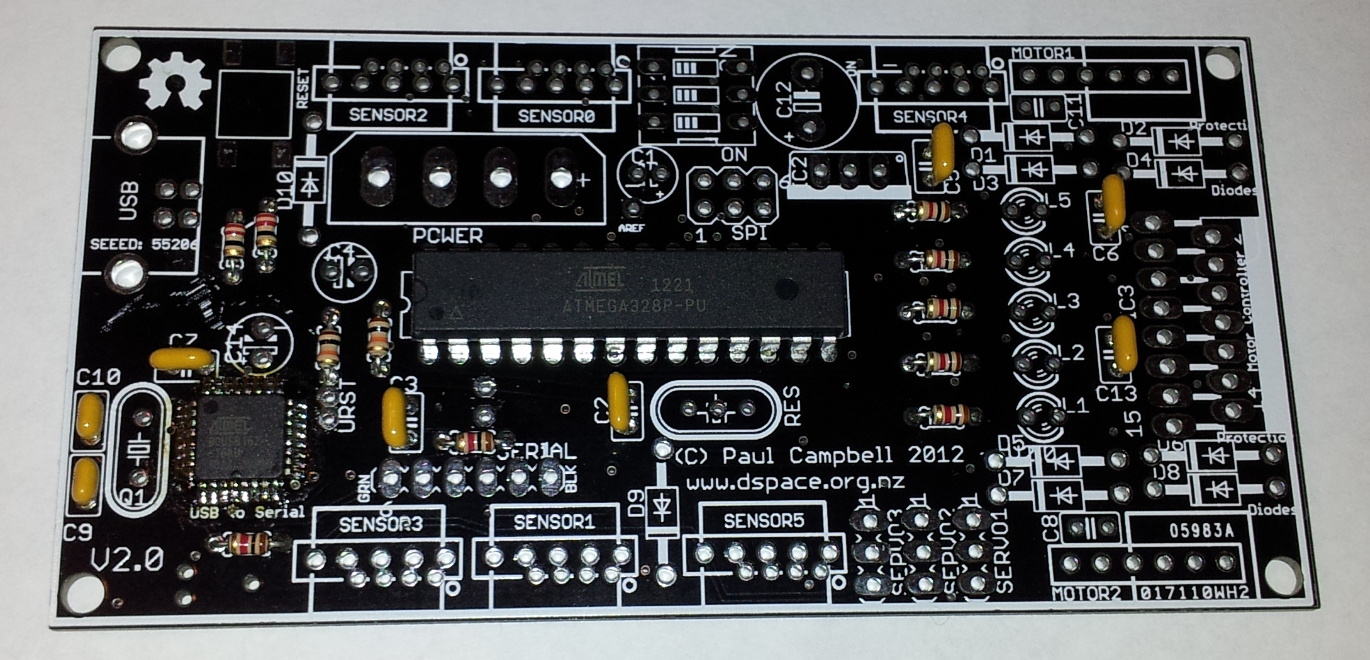
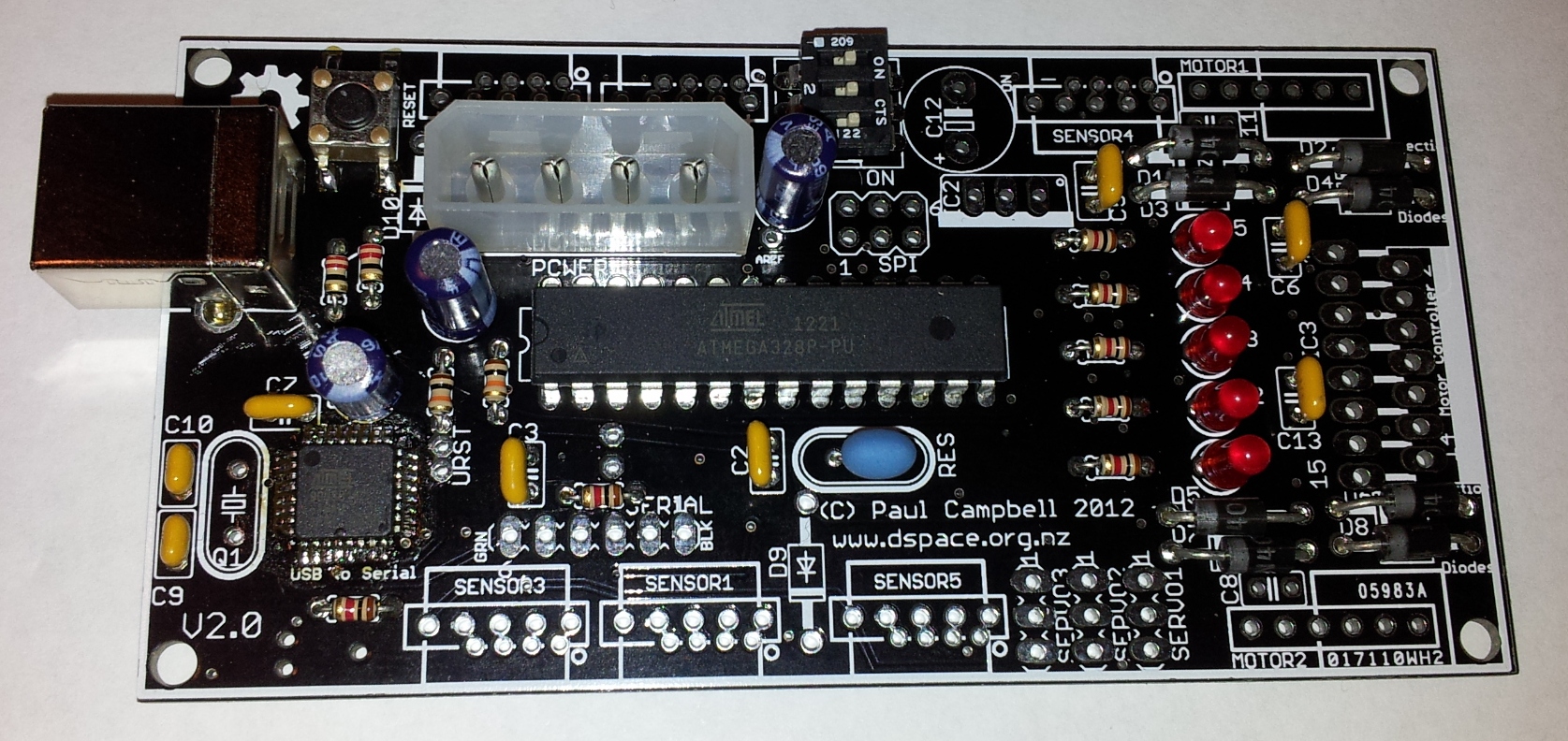
Here's what the finished board looks like
Not every spot in the board will have have a component yet - that's OK, there are lots of options for later expansion - in particular the following spots should be empty:
You will have some components left over - connectors for sensors - you have lots of options, don't solder them in yet, wait until you have decided how you will use them, it's hard to unsolder components, you might damage the board.
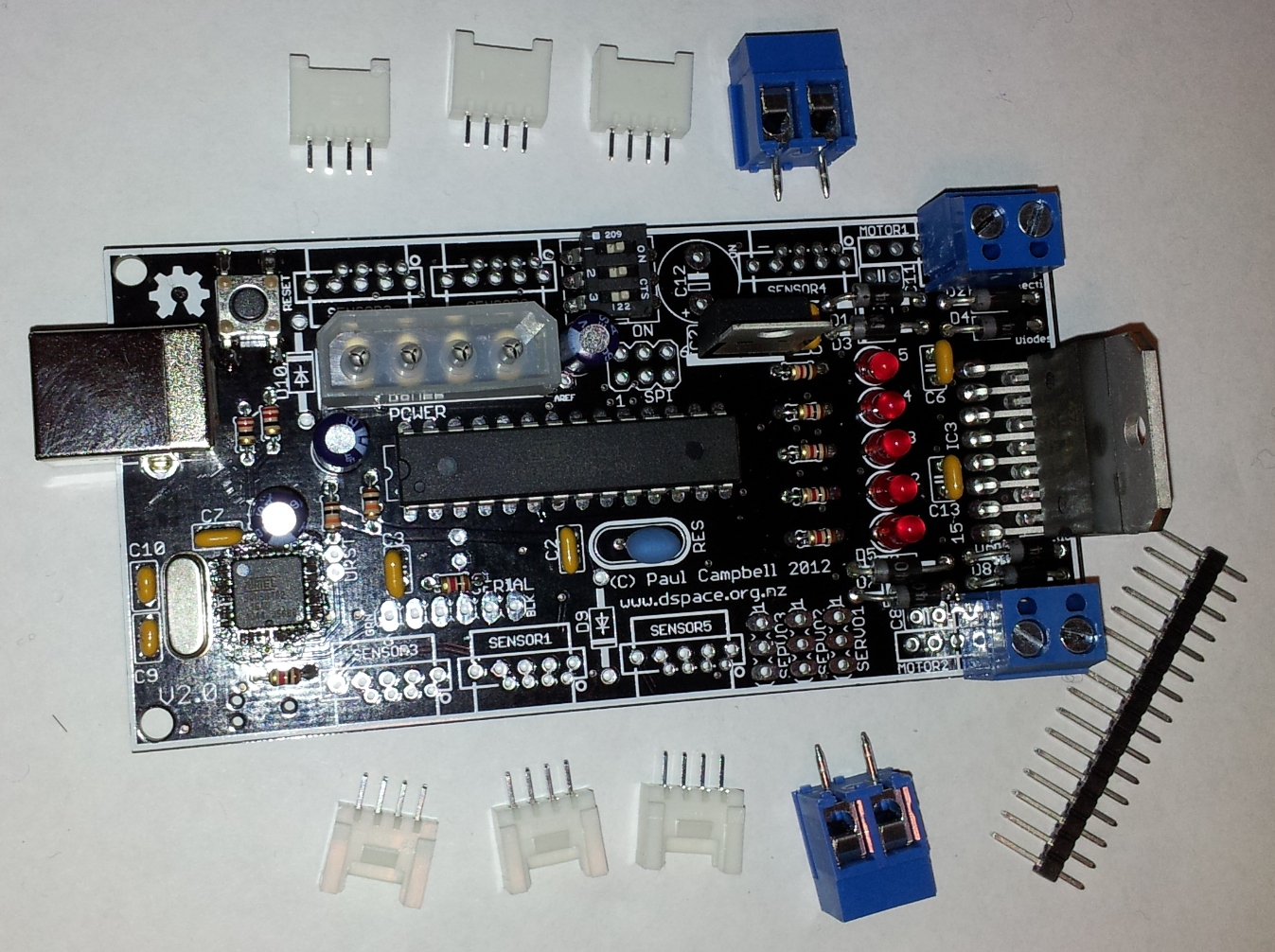
You should have:
Each of the 6 sensors consists of 5 pins on 0.1 inch centers and 4 pins on 2mm centers, there's a longer description below on how they work below. You have 4 basic options for how you use the sensors:
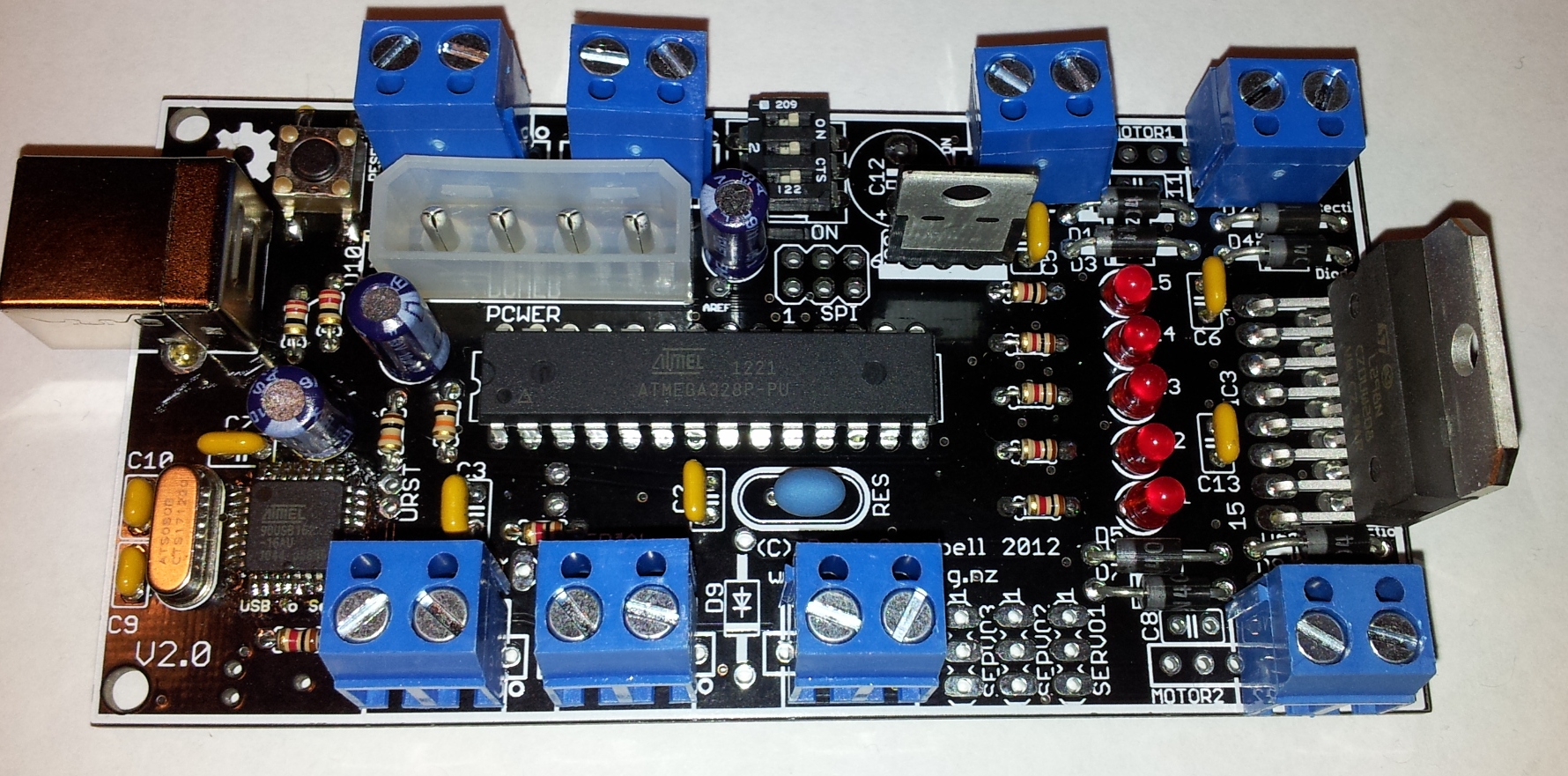
Terminal blocks must be soldered into the middle of thye 0.1 inch pins on each sensor - again look at the layout on the top to see where it should go, again make sure the holes for wire on the side of the block face outwards:
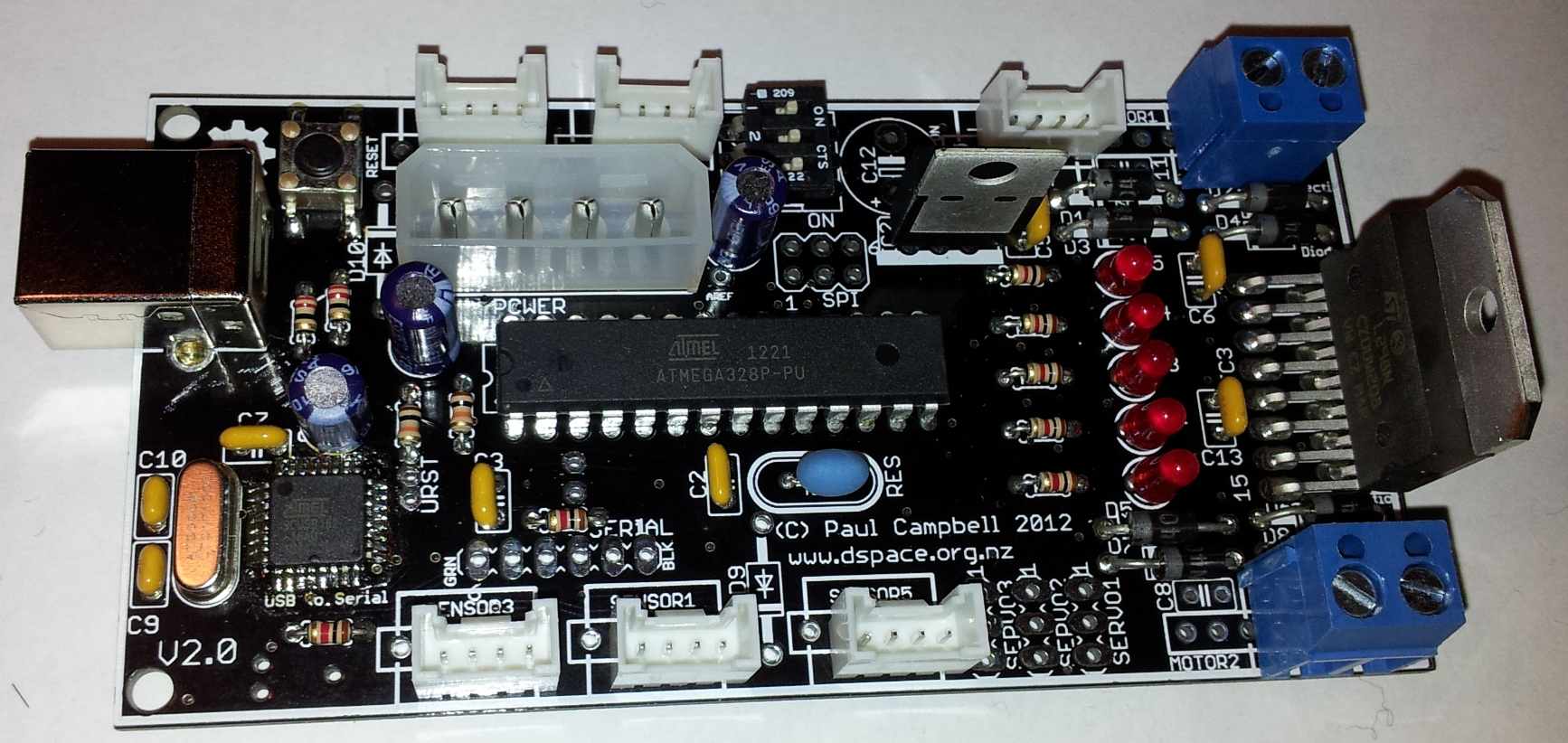
The 4 pin 2mm sockets go in the 2mm holes in each sensor - which way around they go is important - look at the picture below - the open side faces up on BOTH sides of the board (they will NOT be symetrical). The plastic on these sensors melts easily - tape the connectors in place while you are soldering them and use the smallest possible solering time you possibly can. It's also worth adding a tiny drop of super glue to glue the plastic part of the connector to the board - be carefull when you do this.
The power connector is the same one that a computer uses for it's disk drives - you can use a PC power supply for testing if you wire it to be on all the time
Or you can take a disk drive connector and some wire from an old dead power supply (one may give you 3 or 4 cables) - cut the red wire off and wire the yellow wire to positive and the black to negative of a power source somewhere between 9 and 12 volts - a 9v battery will do great for testing.
You're done - go back over your work and check it, look for any shorts or iffy connections
Let's get the basic functionality working first - plug in the power and turn on the power switch (switch 3 of the 3 bit DIP switch) - at this point the default program on the CPU should spring to life and the LEDs should cycle
Next you need to start programming the board - move to the programming page.