This section is a work in progress - I'll add more as fast as I can - the board is a platform for doing many things.
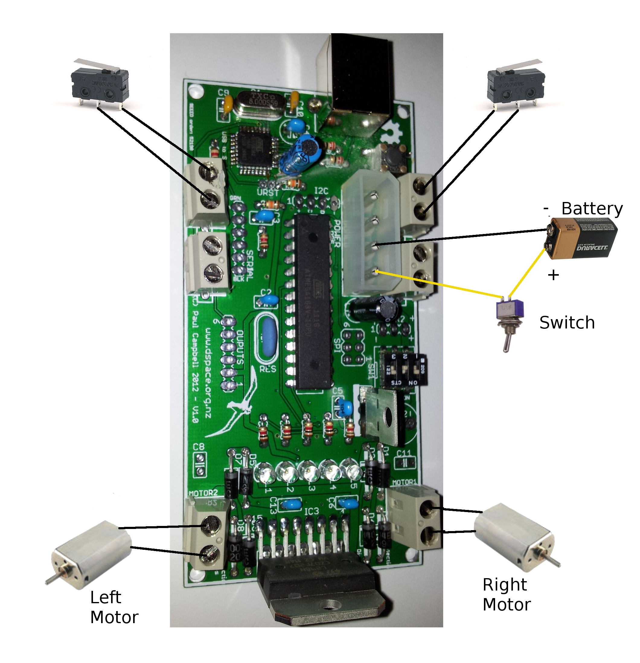
Here's an example of how to wire up the simplest robot - one with two microswitches (code for it is below)
The board has 6 sensor connectors - they can be used 4 alternate ways
The 4-pins are (from the USB plug end of the board): GND, +5V, ANALOG, DIGITAL. 'ANALOG' is only actually a real analog input on sensors 0-3, 'DIGITAL' might also be an analog pin on some connectors, the 'ANALOG' pin can be programmed to be a digital i/o pin if you like. The 5th pin on the 0.1 inch holes is a common analog (or i2c data) pin. The Arduino pin numbers are:
| Sensor | Type | Chip pin | ANALOG pin# | DIGITAL pin# | Notes |
| SENS0 | Analog | PC0 23 | 0 | 14 | |
| Digital | PB0 14 | 8 | shared with SENS5 analog, SERVO 1 LED 3 | ||
| SENS1 | Analog | PC1 24 | 1 | 15 | |
| Digital | PD2 4 | 2 | shared with DIP switch 1 | ||
| SENS2 | Analog | PC2 25 | 2 | 16 | |
| Digital | PC5 28 | 5 | 19 | hardware i2c SCL | |
| SENS3 | Analog | PC3 26 | 3 | 17 | |
| Digital | PD3 5 | 3 | shared with DIP switch 2 | ||
| SENS4 | Analog | PB4 18 | 12 | shared with SPI MISO | |
| Digital | PB3 17 | 11 | shared SPI MOSI | ||
| SENS5 | Analog | PB0 14 | 8 | shared with SERVO 1, LED 3, SENS0 | |
| Digital | PB5 19 | 13 | shared with SERVO 2, SPI SCK | ||
| COMMON | Digital | PC4 27 | 4 | 18 | shared with SERVO 3, hardware i2c SDA |
NOTE: these pin assignments may change on future versions of the board - use the robot library to access these pins rather than accessing them directly
Because the CPU has limited pins, and we're tryed to provide as many possible options as possible, some pins are over committed - but not all sensors need all their pins - that means, for example, that you can't use SENSOR5 at the same time as you use all 3 servos, or SENSOR1's second pin and DIP switch 1, or SENSOR3's secnd pin and DIP switch 2 - plan ahead and choose sensors that don't collide with other functionality. Some basic rules of thumb:
There is a 6 pin header where an SPI but can be connected - this is the standard header used by Atmel programmers - it provides the usual SPI pins plus reset power and ground - it shares pins with sensor inputs.
There are 3 servo connectors on the board - each connector has 3 pins - power, ground and signal - except for SERVO3 the signal pin is shared with SENS5. There are many standards for servo connector layout - connecting a servo wrongly can damage it or the board - we support 3 of the 4 most common types of servos:
| Pin | Function | Futaba | Hitech | JR |
| 1 | Ground | black | black | black/brown |
| 2 | +V | red | red | red |
| 3 | signal | white | yellow | orange |
We do NOT directly support Airtronics servos - if your servo does not have a RED wire in the middle you may have to make a special cable to reorder the wires
Please use the servo interface in the robot library rather than driving servos directly
The 3-pin DIP switch on the board provides a simple on/of switch for the main power supply (switch 3) - we suggest that you add an easier to use external switch to your robot, so you can chase it across the room and turn it off more easily and leave this switch on all the time.
We reccomend that you choose one of the switches (or, better yet, an external switch connected to a sensor port) to disable your robot's motors in software - that way it wont run away from you when you have it tethered to the USB cable to program it
The other two switches 1 and 2 are connected to sensor inputs and can be sampled using the robot library - see above
There are two motor connectors - I suggest you stuff them with the 0.2 inch pitch terminal blocks provided - if you choose not to there are also 0.1-inch pitch holes for simple terminal strips. You can't damage a DC motor by plugging it in backwards - the worst thing will happen is that it goes in reverse, if so just switch the pins.
The motor controller has some limitations you must consider when choosing motors and batteries - have a look at our Systems page for more information
If you have particularly sparky motors, or find you are having problems with the CPU resetting when the motors run (because your power supply is poorly regulated, or can't provide enough current), you can install 0.1uF capacitors in C8 and C11. You can also install a larger capacitor, perhaps 100uF or larger, in C12. If this fails you may need better batteries, or smaller motors.
The motor controller IC is an L298 dual h-bridge motor controller- this will drive two DC motors in either forwards or backwards directions. The L298 is powered by the incoming power (6-12v, not the regulated 5v) choose a voltage to suit your motors, read the above data sheet link to make sure you don't over drive the L298.
There are two motor controllers in the L298 - each can drive a motor forwards, backwards or stop it - three pins - ENABLE, A, and B control the motor:
| Function | Motor 1 Pin# | Motor 2 Pin# |
| ENABLE | 4 | 5 |
| A | 6 | 9 |
| B | 7 | 10 |
And they control the motor this way:
| ENABLE | A | B | Action |
| 0 | - | - | off |
| 1 | 0 | 0 | brake |
| 1 | 0 | 1 | forward |
| 1 | 1 | 0 | reverse |
| 1 | 1 | 1 | brake |
Here's some simple sample code showing how to control motors with an L298. However we recommend that instead of driving the motor controller directly you use the robot library