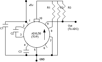
This page describes how to add an accelerometer to your flight computer. The 'standard' one everyone seems to be using is the ADXL50 from Analog Devices it even has a data sheet on line. It measures acceleration between -50G and +50G (a similar part the ADXL05 - data sheet also online - does +/- 5G) and produces an analog signal suitable for driving an ADC such as the ADC1034. To hook it up use the following diagram:
Note that the capacitors should be mounted as physically close to the part as possible - the part is very sensitive to supply noise you may have to further bypass the board's 5V line. Pin 10 has a tab next to it. The arrow shows the direction of sensitivity - if you mount it on a PCB such as the flight computer then when the board is mounted in your rocket the tab should point straight up (or down). All resistors should be 1% (these resistors controll the gain on the output amp, getting exact values is hard - an approximation will work OK but the output voltage/gain will be off a bit - I've put commonly available equivalents in parentheses in the list below).
Parts list:

	R1	49.9k	(47k)
	R2	274k	(270k)
	R3	105k	(100k)
	C1	0.1uF	(disc ceramic)
	C2	0.022uF	(disc ceramic)
	C3	0.022uF	(disc ceramic)
Calibrating the part (at least initially it's easy) - the output is linear over the range +/-50G - accuracy is 0.2% (ie 8-9 bits of your ADC - discard the lower bits). Turn on your computer and orient it with the ADXL50 tab side up - take a measurement this is +1 G - turn it 90 degrees - take another measurement - this is 0G, turn it upside down (ADXL50 tab down) this is -1 G.
No special software is required to listen to the ADXL50 other than whatever you use for your ADC.
Where do you get them? Good question - I don't have an answer yet.