Tiny Tapeout Course 1st Lesson - Verilog
Paul Campbell - Jan 2023
paul@taniwha.com @moonbaseotago

(C) Copyright Moonbase Otago 2023
All rights reserved
Before you start
Install on your laptop:
Linux debian users may just "sudo apt-get iverilog gtkwave" or equivalents for your distro
Things to Learn
- Simulation vs. Hardware
- Flops vs combinatorial logic
- Synchronous Logic
- Modelling with Verilog
We assume you have some exposure to programming.
Simulation vs. Hardware
Of course our goal here is to make some hardware - in the real world big chips cost millions to make and take many months to be built so our boss wants us to get it right the first time so we start by doing lots of simulation.
Verilog is a language that can be compiled into code for simulation and into a bitstream to program an FPGA, or to gates when we make chips
We call compiling into gates "synthesis"
Flip Flops
A "flip flop" is a digital storage element, each one stores a bit it takes a new value on the rising (or falling edge) of a clock. There are lots of different sorts of flops, really you don't need to know the differences, your synthesis tool will choose the best one for you. The simplest sort of flop is a "D flip flop"

It has a 'D' and a 'Q' output, sometimes there's an inverted copy of the Q output Q-bar or Q*.
When the clock input (the one by the little triangle) rises from 0 to 1 the value at D is copied to Q and Q stays constant until the next time the clock rises again.
So long as the input to D is stable for a short time before the clock changes and for a short time after D flops are reliable. We call these times "setup" and "hold" resp.
Synchronous Logic
Most digital logic consists of a bunch of flops driving some combinatorial logic which in turn is stored in some other flops. In simple circuits all the flops share a single clock.

How fast a circuit goes (how fast its clock can be) depends on the longest path in the logic cloud between flops
Pipelines
We can make things faster by creating pipelines where a problem is broken up into smaller pieces processing twice as much data in each clock
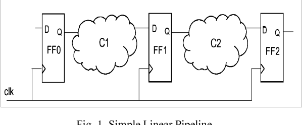
When you're trying to design logic you need to be thinking about the underlying hardware that's being made in terms of clocks and flops/storage
Verilog
Verilog is one of the more popular hardware design and modelling languages - it looks a lot like C (with begin/end instead of { } )
System Verilog is a newer version of Verilog, we're not learning that today, Verilog is a subset of SV
There are a bunch of Open Source Verilog compilers and interpreters, in particular Icarus Verilog (what we're using today) and Verilator (faster but harder to set up)
Verilog - synthesis vs. testing
We use Verilog to create chips, but we also use it to test our chip models. Mostly we're going to concentrate on the subset of the language that we use for designing chips - we call this the "synthesisable subset"
Verilog can be extended using C (and python/etc) using plugins, these things are not synthesisable - and look like subroutine calls that start with a '$' - for example C stdio can be used in a test fixture using $fopen()/$fread() etc
Verilog - modules
Verilog is an object oriented language - its objects are called 'modules' - unlike most modern object oriented languages Verilog are only created statically at compile/synthesis time - unlike C++ we can't just 'new' up some more gates on the fly
Modules are only connected with wires - here's a simple example
    module invert(input in, output out);

        assign out = !in;

    endmodule

    module buffer(input a, output b);

	wire tmp;
        invert x(.in(a), .out(tmp));
        invert y(.in(tmp), .out(b));

    endmodule
Verilog - modules 2
- 'module X();' defines a module, can only be defined once
- 'X name()' instantiates a module, can be instantiated many times
- 'input a, output b' is a list of wires connecting the module to the outside world - you can also use 'inout' but that's not synthesisable
- when you instantiate a module you can hook up its inputs and outputs by name - for example '.in(a), .out(tmp)' - you can do it other ways but doing it by name is good practice
Verilog - bits
At its lowest level everything in verilog is a bit, or built from bits - there are two basic sorts:
- wires - we've already seen these, they're used to connect modules together and to represent combinatorial logic - they are driven from only one place (for synthesisable models) with an 'assign' statement and can be sampled in multiple places.
- regs - these are more like variables in more traditional languages. They are assigned in a similar way, however they can be used to model both wires and flip-flops - more about this later.
	wire a, b, c;
	reg  gg, hh, ii;
Bits can have 4 different values '0' '1' 'x' and 'z' - x and z mean 'invalid' and 'tristate', we really only care about 'x' - wires that aren't driven, or regs that aren't initialised start with 'x' (not in the real world), x can also be used to tell the synthesis tool when we don't care what it does
Verilog - vectors
regs and wires can be collected into vectors - their size is given by the lowest and highest bit numbers.
We can use [hi:lo] to pick bits out of a vector. And {} to collect bits to make a wider vector
    input [31:0]bus,	       	// 32 bit bus
    output [15:0]hi_byte_data,  // 16 bits

    wire [7:0]hi_byte;		// 8 bits
    reg [7:0]data;
    assign hi_byte = bus[31:16];   // selection lets us pick bits
    assign hi_byte_data = {hi_byte, data}; // {} collects bits
Verilog - module parameters
When modules are instantiated you can pass in parameters:
    module adder(input [WIDTH-1:0]in1, input [WIDTH-1:0]in2,
		 output[WIDTH-1:0]out);

        parameter WIDTH=4;	// 4 is the default

        assign out = in1+in2;

    endmodule

    ....
        addr #(.WIDTH(8))add8(.in1(in1), ...);
Verilog - constants
Verilog has lots of ways to make constants - you can just use numbers and you get 32-bit wide decimal numbers.
More generally constants are size ' base value
size is the width in bits if omitted the size is 32
base can be one of 'bdoh' for binary/decimal/octal/hex
value is a bunch of appropriate digits or letters for the base, also 'x' or 'z', '_' can be imbedded in values it is ignored
	12'b1111_0101_xxxz
	32'd934
	6'o34
	16'h12x4
Verilog - expressions
As we mentioned wires are driven with an 'assign' statement - the thing on the left of the '=' must be a wire, a selection of a wire vector or a collection {} of wires
The thing on the right is an expression, much like one you might use in C (so long as you are careful about sizes, including:
- + - * / % - math
- & | ^ && || - logic
- ( ? : ) - mux
- + - - unary math
- ~ ! & | ^ - unary logic
- name[] {,} - bits select/concat
- name - wire or reg value
- constant
Some operations (* / %) are very expensive and may not be synthesisable in many places, others (+ and -) should be used with care
Interlude - some non synthesisable code: 'initial' means 'do this at the start' $dumpfile says store trace data in a file called "test.vcd" $dumpvars says start storing trace data #10 means wait 10 time units forever just means loop forever OK - this is the most important bits of the whole course many of the rules given in the following pages are constraints to make synthesis work well and are not parts of Verilog itself. reg variables can be used to model complex combinatorial logic, OR to model flip-flops - we use different types of always statements to signal which An always statement is part of a module that assigns values to reg variables - 'always' is essentially shorthand for 'initial forever' - synthesisable forms of always are followed by an event wait - there are two basic forms: The @(*) means "wait for something to change that would effect the result" We use this form of the always statement to model combinatorial logic - note that we always use '=' to assign to regs being used to model combinatorial values. Each reg used this way must only be in one always statement Each pass (every path) through the always statement must assign something to the reg - otherwise synthesis will make a spurious latch @(posedge clk) is used when we are assigning values to regs that are to be flip-flops - the statements are only executed when the clock signal transitions from 0 to 1 We always use the <= assignments when assigning to regs in these always blocks, never mix = and <= These always blocks are usually simple, trying to make them too complex can get you into trouble. We us <= because it helps us make pipelines. When an assignment is executed a copy of what is on the right is made, the assignment to the reg doesn't occur until after all the always statements triggered by that clock edge have been processed Statements are executed in order and are separated by ; begin/end surround blocks to group statements if-then or if-then-else can be used to only execute some statements for and while can be used to iterate over bits - care must be taken to by synthesisable (I seldom use them) case-endcase and casez-endcase are very useful Combinatorial logic: Flip-flops: We're about done - some quick notes about best practices:Verilog - a test fixture
    module test;
        reg clk, reset;
        initial begin
                $dumpfile("test.vcd");
                $dumpvars;
		reset = 1;
		clk = 0;
		#10 clk = 1;
		#10 clk = 0;
		#10 clk = 1;
		#10 clk = 0; reset = 0;
		forever #10 clk = ~clk;
	end
	model top(.clk(clk), .reset(reset), ....);
    endmodule
Verilog - always statements
    reg r;

    always @(*)
         r = expression;

    always @(posedge clk)
         r <= expression;
Verilog - always @(*)
Verilog - always @(*) - examples
    wire [7:0]w;	// these are the same
    assign w = a+1;

    reg [7:0]w;
    always @(*) w = a+1;

    reg [7:0]r_w, c_w;	// combinatorial part of a counter
    always @(*) begin
	c_w = r_w;
	if (reset) begin
	    c_w = 0;
	end else
	if (count) begin
	    c_w = r_w+1;
	end
    end
Verilog - always @(posedge clk)
Verilog - always @(posedge clk) - example
    reg [7:0]count;
    always @(posedge clk) begin
        if (reset) begin
            count <= 0;
        end else
        if (step) begin
            count <= count+1;
        end
    end
'
Verilog - always @(posedge clk) - example
    reg [7:0]a, b, c;

    always @(posedge clk) begin  // these two are the same
        a <= in;
        b <= a;
        c <= b;
    end

    always @(posedge clk) begin
        c <= b;
        b <= a;
        a <= in;
    end
Verilog - statements
    case (exp)
    1: statement-1;
    2: statement-2;
    default: statement-3;
    endcase

    casez (exp)	// casez allows wild cards
    3'b1??: statement-1;
    3'b01?: statement-2;
    3'b001: statement-3;
    default: statement-4;
    endcase
Verilog - Summary
Verilog - best practices
Verilog - best practices
module count(input clk, input reset, input count,
	     output[WIDTH-1:0]out);

    parameter WIDTH=8;
    reg [WIDTH-1:0]r_w, c_w;
    assign out = r_w;

    always @(*) begin
	c_w = r_w;
	if (reset) begin
	    c_w = 0;
	end else
	if (count) begin
	    c_w = r_w+1;
	end
    end

    always @(posedge clk) begin
	r_w <= c_w;
    end

endmodule
Verilog - exercises